From Rii
m |
|||
| (4 intermediate revisions not shown) | |||
| Line 17: | Line 17: | ||
* Illumination should to be integrated into the robot. | * Illumination should to be integrated into the robot. | ||
| - | To meet the challenges of SPA surgeries, an Insertable Robotic Effector Platform (IREP) shown in the figure is designed by merging enabling technologies of endoscopic imaging (Hu, Allen et al. 2007; Hogle, Hu et al. 2008; Hu, Allen et al. 2008; Hu, Allen et al. 2008) and distal dexterity enhancement (Kapoor, Simaan et al. 2005; Simaan 2005; Xu and Simaan 2006; Xu and Simaan 2008; Simaan, Xu et al. 2009) | + | To meet the challenges of SPA surgeries, an Insertable Robotic Effector Platform (IREP) shown in the figure is designed by merging enabling technologies of endoscopic imaging (Hu, Allen ''et al.'' 2007; Hogle, Hu ''et al.'' 2008; Hu, Allen ''et al.'' 2008; Hu, Allen ''et al.'' 2008) and distal dexterity enhancement (Kapoor, Simaan ''et al.'' 2005; Simaan 2005; Xu and Simaan 2006; Xu and Simaan 2008; Simaan, Xu ''et al.'' 2009) |
| - | + | ||
| - | + | ||
The IREP robot consists of two five-DoF snake-like continuum robots, two two-DoF parallelogram mechanisms, and one three-DoF stereo vision module. It is designed to meet the challenge of enabling abdominal SPA procedures, such as cholecystectomy, appendectomy, liver resection, etc. When it is in its folded configuration, it can be deployed into the abdomen through an Ø15mm skin incision while using its forward-looking stereo vision module to guide surgeons through the insertion phase. The IREP can then unfold itself into a working configuration to perform SPA procedures after being deployed. | The IREP robot consists of two five-DoF snake-like continuum robots, two two-DoF parallelogram mechanisms, and one three-DoF stereo vision module. It is designed to meet the challenge of enabling abdominal SPA procedures, such as cholecystectomy, appendectomy, liver resection, etc. When it is in its folded configuration, it can be deployed into the abdomen through an Ø15mm skin incision while using its forward-looking stereo vision module to guide surgeons through the insertion phase. The IREP can then unfold itself into a working configuration to perform SPA procedures after being deployed. | ||
| Line 27: | Line 25: | ||
* The stereo vision module has a pair of CCD cameras for depth perception as well as surgical tool tracking. It has three degrees of freedom for pan, tilt, and zoom. A light source using optic fiber bundles is also integrated. | * The stereo vision module has a pair of CCD cameras for depth perception as well as surgical tool tracking. It has three degrees of freedom for pan, tilt, and zoom. A light source using optic fiber bundles is also integrated. | ||
* All these controlled joints will be actuated by NiTi tubes or stainless steel rods in push-pull mode. The actuation unit will remain outside patient’s body. | * All these controlled joints will be actuated by NiTi tubes or stainless steel rods in push-pull mode. The actuation unit will remain outside patient’s body. | ||
| + | |||
| + | [[File: Research_IREP2007_2.jpg|thumb|360px|The control system hierarchy for the IREP robot]] | ||
The control system of the IREP robot uses a host-target environment powered by xPC Target™ from The MathWorks, Inc, which provides a rapid prototyping approach for control system setup in an open hardware architecture. | The control system of the IREP robot uses a host-target environment powered by xPC Target™ from The MathWorks, Inc, which provides a rapid prototyping approach for control system setup in an open hardware architecture. | ||
| Line 32: | Line 32: | ||
The planned control hierarchy is presented in the figure to the right. A GUI running on the host PC takes motion inputs from two master manipulators and then sends them down to the target PC via ethernet connection after scaling and mapping. Target PC processes the desired motions of the IREP robot by solving kinematics and redundancy resolution in a 1kHz servo control loop. A third PC running vision processing module will output the stereo display for surgeons and feed tool tracking results to the host PC for motion compensations of the IREP’s dual snake-like arms. | The planned control hierarchy is presented in the figure to the right. A GUI running on the host PC takes motion inputs from two master manipulators and then sends them down to the target PC via ethernet connection after scaling and mapping. Target PC processes the desired motions of the IREP robot by solving kinematics and redundancy resolution in a 1kHz servo control loop. A third PC running vision processing module will output the stereo display for surgeons and feed tool tracking results to the host PC for motion compensations of the IREP’s dual snake-like arms. | ||
| - | A simulation of the IREP robot is shown, demonstrating different operation modes during the insertion configuration and the working configuration. | + | A simulation of the IREP robot is shown below, demonstrating different operation modes during the insertion configuration and the working configuration. |
| - | + | [[File: Research_IREP2007_3.gif|thumb|640px|center|Deployment of the IREP robot]] | |
Latest revision as of 08:28, 5 October 2014
An Image-Guided In-Vivo Tooling Platform for Minimal Access Surgery
September 2007 to August 2009
![]() This work was done when Dr. Kai Xu was with the Advanced Robotics & Mechanism Applications Lab, Department of Mechanical Engineering, Columbia University under a collaboration with Robotics Lab, Department of Computer Science, Columbia University.
This work was done when Dr. Kai Xu was with the Advanced Robotics & Mechanism Applications Lab, Department of Mechanical Engineering, Columbia University under a collaboration with Robotics Lab, Department of Computer Science, Columbia University.
A robotic system for the Single Port Access (SPA) surgeries should be capable at least doing the following:
- The robot should have a folded configuration so that it can pass through a single small skin incision;
- The robot should be self deployable into a working configuration;
- The robot can manipulate target organs and their related tissues (such as gallbladder, hepatic tissues, pancreas, etc.) with enough precision and payload;
- End effectors of the robot can be independently replaced during operations for different tasks;
- The translational workspace should be bigger than 50mm×50mm×50mm (size of target organs);
- The robot should posses a stereo vision unit for depth perception and tool tracking;
- Illumination should to be integrated into the robot.
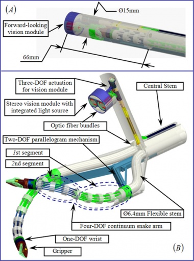
To meet the challenges of SPA surgeries, an Insertable Robotic Effector Platform (IREP) shown in the figure is designed by merging enabling technologies of endoscopic imaging (Hu, Allen et al. 2007; Hogle, Hu et al. 2008; Hu, Allen et al. 2008; Hu, Allen et al. 2008) and distal dexterity enhancement (Kapoor, Simaan et al. 2005; Simaan 2005; Xu and Simaan 2006; Xu and Simaan 2008; Simaan, Xu et al. 2009)
The IREP robot consists of two five-DoF snake-like continuum robots, two two-DoF parallelogram mechanisms, and one three-DoF stereo vision module. It is designed to meet the challenge of enabling abdominal SPA procedures, such as cholecystectomy, appendectomy, liver resection, etc. When it is in its folded configuration, it can be deployed into the abdomen through an Ø15mm skin incision while using its forward-looking stereo vision module to guide surgeons through the insertion phase. The IREP can then unfold itself into a working configuration to perform SPA procedures after being deployed.
- Each snake-like continuum robot includes four components: i) a gripper, ii) a one-DoF rotational wrist, iii) a four-DoF continuum snake arm and iv) a flexible stem. It acts as a surgical telemanipulation slave for dual arm interventions and delivery of sensors (e.g. ultrasound probe) or energy sources (e.g. cautery). During SPA procedures, each of the arms of the IREP robot can be independently pulled out and replaced with another arm equipped with different surgical end effectors.
- Each parallelogram mechanism has two degrees of freedom for a translational placement of the snake-like continuum robot. The flexible stem will be independently fed in and out to comply with the parallelogram’s motion.
- The stereo vision module has a pair of CCD cameras for depth perception as well as surgical tool tracking. It has three degrees of freedom for pan, tilt, and zoom. A light source using optic fiber bundles is also integrated.
- All these controlled joints will be actuated by NiTi tubes or stainless steel rods in push-pull mode. The actuation unit will remain outside patient’s body.
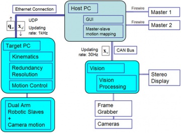
The control system of the IREP robot uses a host-target environment powered by xPC Target™ from The MathWorks, Inc, which provides a rapid prototyping approach for control system setup in an open hardware architecture.
The planned control hierarchy is presented in the figure to the right. A GUI running on the host PC takes motion inputs from two master manipulators and then sends them down to the target PC via ethernet connection after scaling and mapping. Target PC processes the desired motions of the IREP robot by solving kinematics and redundancy resolution in a 1kHz servo control loop. A third PC running vision processing module will output the stereo display for surgeons and feed tool tracking results to the host PC for motion compensations of the IREP’s dual snake-like arms.
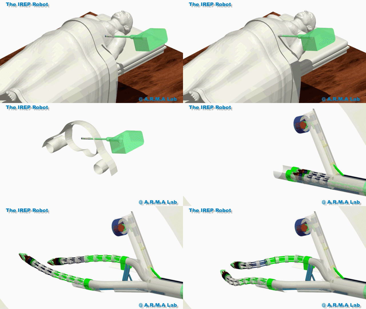
A simulation of the IREP robot is shown below, demonstrating different operation modes during the insertion configuration and the working configuration.


