From Rii
| (10 intermediate revisions not shown) | |||
| Line 4: | Line 4: | ||
January 2005 to August 2009 | January 2005 to August 2009 | ||
| - | [[image:note_bulb.png|text-bottom|12px]] This work | + | [[image:note_bulb.png|text-bottom|12px]] This work started when Dr. Kai Xu was with [http://research.vuse.vanderbilt.edu/arma/ the Advanced Robotics & Mechanism Applications Lab, Department of Mechanical Engineering, Columbia University]. |
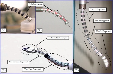
[[File: Research_continuum2004_1.jpg|thumb|380px|Continuum robots involved in this research: (A) a Ø7.5mm one; (B) a Ø4.2mm one; (C) a two-segment continuum robot with a detachable gripper; (D) a three-segment continuum robot with intrinsic force sensing capability]] | [[File: Research_continuum2004_1.jpg|thumb|380px|Continuum robots involved in this research: (A) a Ø7.5mm one; (B) a Ø4.2mm one; (C) a two-segment continuum robot with a detachable gripper; (D) a three-segment continuum robot with intrinsic force sensing capability]] | ||
| - | This continuum structures in this research were introduced by Simaan et al. (Simaan, Taylor et al. 2004; Simaan, Taylor et al. 2004). They consist of one or more flexible segments. Each segment consists of multiple | + | This continuum structures in this research were introduced by Simaan ''et al.'' (Simaan, Taylor ''et al.'' 2004; Simaan, Taylor ''et al.'' 2004). They consist of one or more flexible segments. Each segment consists of multiple super-elastic NiTi components (tubes or rods) called backbones and several rigid disks. The figure to the right shows several examples: insets (A) and (B) show a one-segment continuum robot, inset (C) shows a two-segment continuum robot with a detachable gripper and inset (D) shows a three-segment robot with intrinsic force sensing capability. |
| - | In these examples, each segment includes one primary backbone, three secondary backbones and a few disks. As the figure below shows, the primary backbone is centrally located and three identical secondary backbones are equidistant from each other and from the primary backbone. The primary backbone is attached to the base disk and the end disk, while the secondary backbones are only attached to the end disk and can slide in appropriately toleranced holes in the base disk and in the spacer disks. Two adjacent disks and the backbones form a | + | In these examples, each segment includes one primary backbone, three secondary backbones and a few disks. As the figure below shows, the primary backbone is centrally located and three identical secondary backbones are equidistant from each other and from the primary backbone. The primary backbone is attached to the base disk and the end disk, while the secondary backbones are only attached to the end disk and can slide in appropriately toleranced holes in the base disk and in the spacer disks. Two adjacent disks and the backbones form a sub-segment. Each segment possesses two degrees of freedom (DoF) via simultaneous actuation of the three secondary backbones in a push-pull mode. Since three secondary backbones are independently actuated to carry out a 2-DoF motion, these continuum robots feature actuation redundancy. |
| - | [[File: Research_continuum2004_2.jpg|thumb| | + | [[File: Research_continuum2004_2.jpg|thumb|300px|left|Structure of one continuum segment]] |
Multiple segments can be serially stacked through the use of concentric NiTi backbones to form a continuum robot with more DoFs. Three segments of the snake-like continuum robot can be stacked and numbered from the proximal end to the distal end. The end disk of the first segment also acts as the base disk of the second segment, while the end disk of the second segment also serves as the base disk of the third segment. Backbones of the first and second segment are concentric superelastic NiTi tubes, while the third segment’s backbones are superelastic NiTi beams passing through the second segment’s tubes. | Multiple segments can be serially stacked through the use of concentric NiTi backbones to form a continuum robot with more DoFs. Three segments of the snake-like continuum robot can be stacked and numbered from the proximal end to the distal end. The end disk of the first segment also acts as the base disk of the second segment, while the end disk of the second segment also serves as the base disk of the third segment. Backbones of the first and second segment are concentric superelastic NiTi tubes, while the third segment’s backbones are superelastic NiTi beams passing through the second segment’s tubes. | ||
| - | According to the modeling framework | + | [[File: Research_continuum2004_3_.gif|thumb|360px|One segment simulated in MATLAB]] |
| + | |||
| + | According to the modeling framework, shape of the continuum segment shown assumes a constant twist distribution. Following the equivalent simplifications below, simplified models for kinematics and statics are derived. | ||
* Shape of the primary backbone is circular. This approximation have been experimentally verified. Analytic modeling using elliptic integrals shows that in one actuation mode, shape of the primary backbone is strictly circular. In the other actuation mode, shape of the primary backbone is very close to circular. | * Shape of the primary backbone is circular. This approximation have been experimentally verified. Analytic modeling using elliptic integrals shows that in one actuation mode, shape of the primary backbone is strictly circular. In the other actuation mode, shape of the primary backbone is very close to circular. | ||
* Shape of the secondary backbones is circular. This approximation will introduce some experiment-based corrections. | * Shape of the secondary backbones is circular. This approximation will introduce some experiment-based corrections. | ||
| - | * Load can be re-distributed among the backbones | + | * Load can be re-distributed among the backbones. This assumption is introduced in (Simaan 2005) by presenting a general resolution for actuation redundancy. Results from the analytic modeling using elliptic integrals show that the tip position variation is less than 0.05% of the segment’s length (while the tip orientation is kept the same) when loads are redistrubited. |
| + | |||
| + | In the following video clips, a 2-segment arm can be tele-operated, whereas a 3-segment arm with force sensing capability is palpating a prostate model for tumor detection. For details, please refer to papers listed in the publication session. | ||
| - | + | {|border="1" align="center" cellpadding="5" | |
| + | |align="center"|'''A 2-segment arm under teleoperation''' | ||
| + | |align="center"|'''A 3-segment arm in palpation''' | ||
| + | |- | ||
| + | |[[Image: Research_continuum2004_5.gif]] | ||
| + | |[[Image: Research_continuum2004_6.gif]] | ||
| + | |} | ||
Latest revision as of 15:43, 6 October 2014
A Continuum Structure as Medical Robotic End Effector
January 2005 to August 2009
![]() This work started when Dr. Kai Xu was with the Advanced Robotics & Mechanism Applications Lab, Department of Mechanical Engineering, Columbia University.
This work started when Dr. Kai Xu was with the Advanced Robotics & Mechanism Applications Lab, Department of Mechanical Engineering, Columbia University.
This continuum structures in this research were introduced by Simaan et al. (Simaan, Taylor et al. 2004; Simaan, Taylor et al. 2004). They consist of one or more flexible segments. Each segment consists of multiple super-elastic NiTi components (tubes or rods) called backbones and several rigid disks. The figure to the right shows several examples: insets (A) and (B) show a one-segment continuum robot, inset (C) shows a two-segment continuum robot with a detachable gripper and inset (D) shows a three-segment robot with intrinsic force sensing capability.
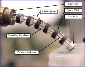
In these examples, each segment includes one primary backbone, three secondary backbones and a few disks. As the figure below shows, the primary backbone is centrally located and three identical secondary backbones are equidistant from each other and from the primary backbone. The primary backbone is attached to the base disk and the end disk, while the secondary backbones are only attached to the end disk and can slide in appropriately toleranced holes in the base disk and in the spacer disks. Two adjacent disks and the backbones form a sub-segment. Each segment possesses two degrees of freedom (DoF) via simultaneous actuation of the three secondary backbones in a push-pull mode. Since three secondary backbones are independently actuated to carry out a 2-DoF motion, these continuum robots feature actuation redundancy.
Multiple segments can be serially stacked through the use of concentric NiTi backbones to form a continuum robot with more DoFs. Three segments of the snake-like continuum robot can be stacked and numbered from the proximal end to the distal end. The end disk of the first segment also acts as the base disk of the second segment, while the end disk of the second segment also serves as the base disk of the third segment. Backbones of the first and second segment are concentric superelastic NiTi tubes, while the third segment’s backbones are superelastic NiTi beams passing through the second segment’s tubes.
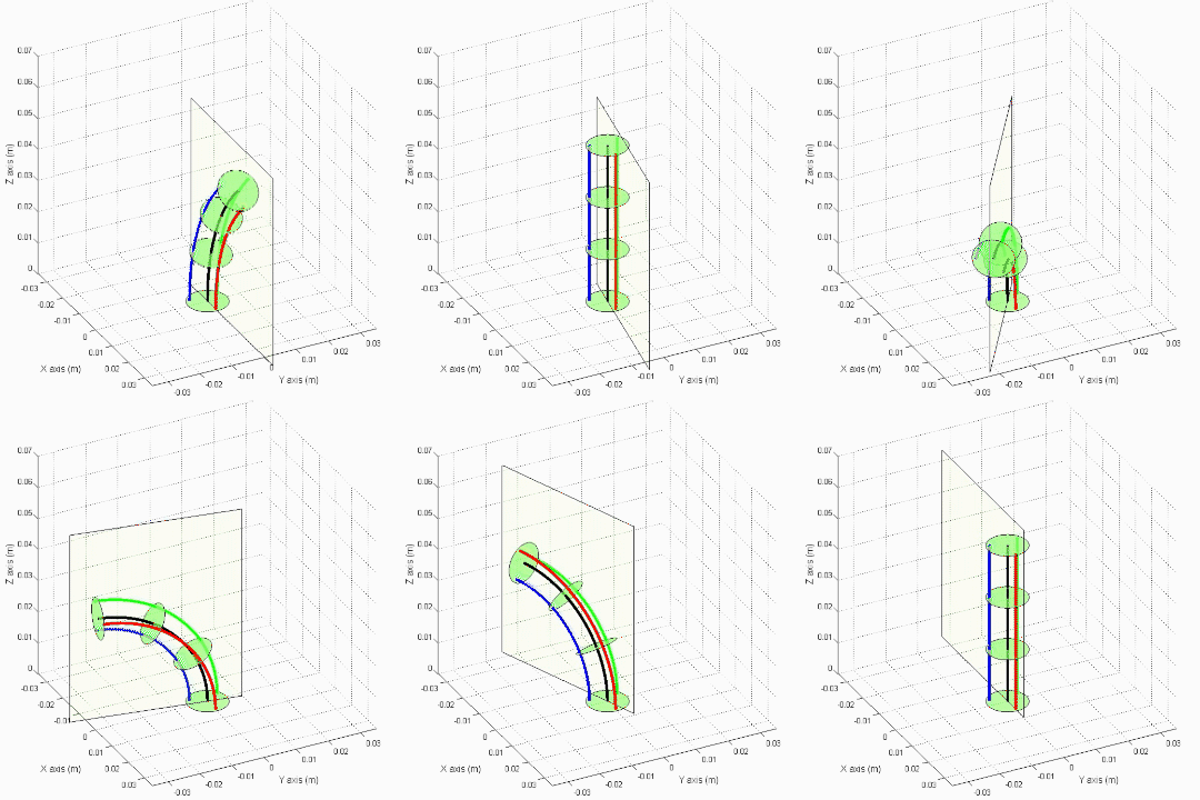
According to the modeling framework, shape of the continuum segment shown assumes a constant twist distribution. Following the equivalent simplifications below, simplified models for kinematics and statics are derived.
- Shape of the primary backbone is circular. This approximation have been experimentally verified. Analytic modeling using elliptic integrals shows that in one actuation mode, shape of the primary backbone is strictly circular. In the other actuation mode, shape of the primary backbone is very close to circular.
- Shape of the secondary backbones is circular. This approximation will introduce some experiment-based corrections.
- Load can be re-distributed among the backbones. This assumption is introduced in (Simaan 2005) by presenting a general resolution for actuation redundancy. Results from the analytic modeling using elliptic integrals show that the tip position variation is less than 0.05% of the segment’s length (while the tip orientation is kept the same) when loads are redistrubited.
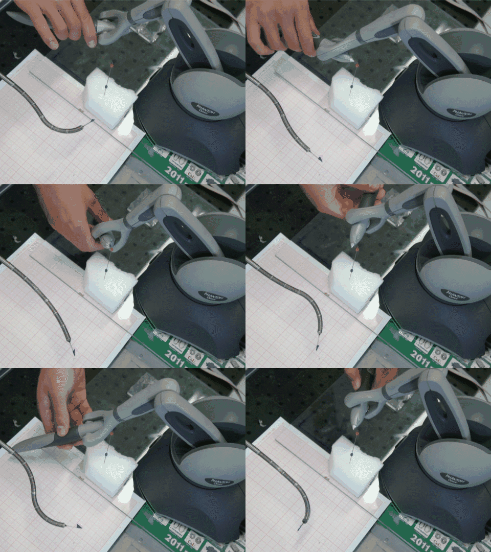
In the following video clips, a 2-segment arm can be tele-operated, whereas a 3-segment arm with force sensing capability is palpating a prostate model for tumor detection. For details, please refer to papers listed in the publication session.
| A 2-segment arm under teleoperation | A 3-segment arm in palpation |

| 
|


